ROBOSUB 2021
QUICK ACCESS
Bot Timeline
Tiburon 1.0
Tiburon 2.0
Tiburon 3.0
Tiburon 4.0
Software Subsystem
Perception Stack
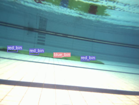
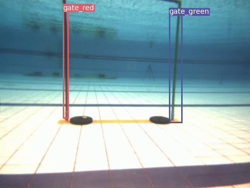
Object Detection
Apart from the preprocessing and postprocessing of the image stream that is done by
OpenCV(an open-source computer vision) library,
we are using Yolo(You Only Look Once, a Convolutional Neural Network(CNN) based on DarkNet architecture) for object detection. This allows
us to accurately identify the objects with complex
textures or shapes from a greater distance. Yolo is
trained on a large dataset of images and videos collected from test runs and past competitions. In addition, we have applied various image augmentations
to impart variations and increase the dataset size.
Preprocessing Techniques
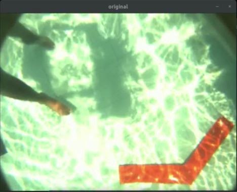
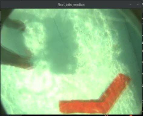
Glare Removal
Sometimes the images obtained from the bottom camera are too bright and keep fluctuating due to sunlight reflection(happens when the arena isn't that deep and has a shiny bottom surface). To remove glares from these images we have used an algorithm to make them more visible and clear.
The algorithm keeps track of the most recent 'n' images and finds the median, mean variation of 'n' RGB values respectively for each pixel in the image. The final image obtained has less glare and the lighting is spread equally. As the glares are rapidly moving due to surface water motion, taking its median helps to distribute its intensity and makes the image more clear and
visible.
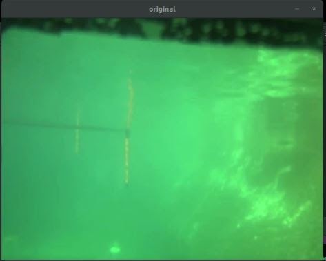
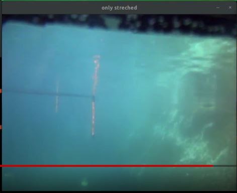
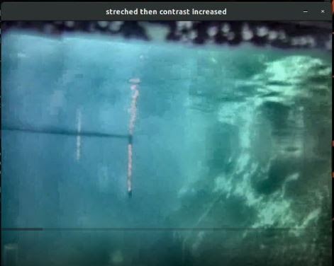
Color Correction
The Robosub arena watercolor is greenish and unclear and thus making things difficult for the object detection model as they are trained on a different environment.
To change the color and make it more natural blue, we have simply changed the weight of the RGB channel of the image (called Stretching ) and obviously, the weight of the green channel needs to be reduced. Then to remove the fogginess in the image we used the Contrast Limited Adaptive Histogram Equalization (CLAHE) algorithm that helped to increase the image contrast and made images more
clear.
Model Optimization
The perception stack is mostly carried out by object detection methods using deep neural networks. However, there has always been a trade-off between accuracy and real-time fps. We have approached this problem with model optimization using quantization by implementing state-of-the-art quantization-aware training methods. This approach simply converts all float32 weights and activations to int8 thus drastically reducing model size as well as the inference time. This enables us to use any low-power computing devices and stack multiple models in our pipeline without compromising
performance.
Stereo Vision
In traditional stereo vision, two cameras, displaced horizontally from one another are used to obtain two differing views on a scene, in a manner similar to human binocular vision. By comparing these two images, the relative depth information can be obtained in the form of a disparity map, which encodes the difference in horizontal coordinates of corresponding image points. Computer vision algorithms are also applied to images for smoothening and rectification of the images. Thus by using stereo vision we can perceive the distance between the object and the camera plane while carrying out various tasks during the
mission.
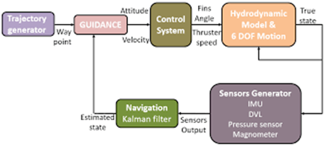
Navigation Stack
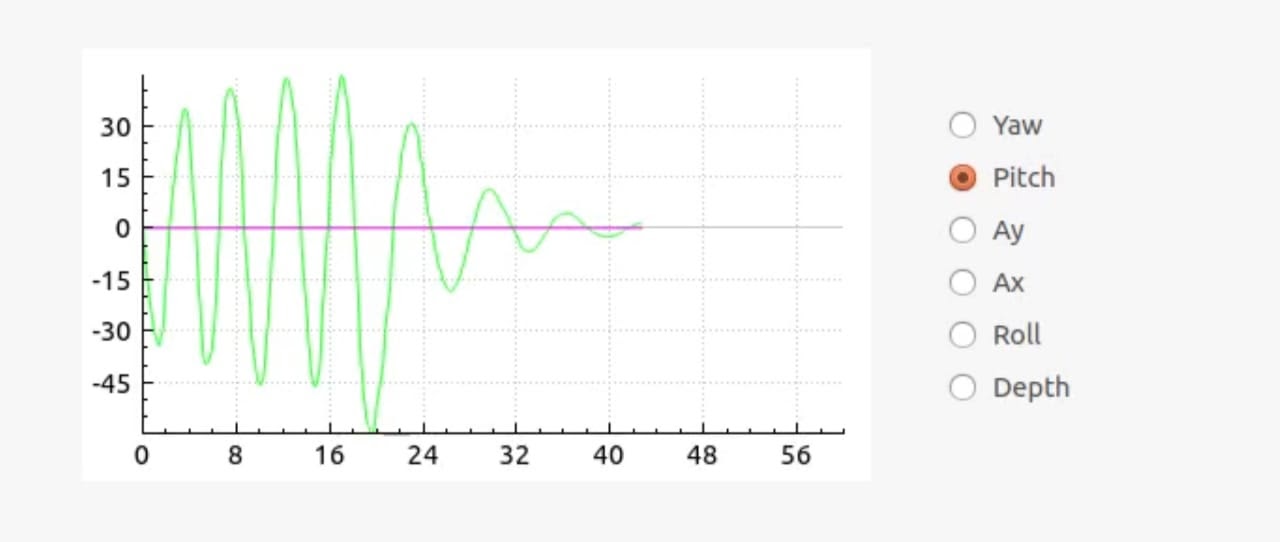
Auto-tuning PID
The PID controllers used in our AUV have to tune it (that means to obtain the value of Kp, Ki, Kd constants ) manually so that it manoeuvres properly.
But this time we tried to automate things and decided to build a tuning algorithm using Ant Colony Optimization (ACO). To tune the constants of each degree of freedom, the algorithm first generates some random values and tries to minimize the error generated from a cost function for each generated value and then determine the best values obtained from this generation and use them as the parents for the next generation. This happens generation over generation till we get an optimal value and every generation is more optimal than its previous
one.
Underwater Localization
Underwater localization has always been a
challenge for AUVs because of the incapability of
inertial sensors to calculate linear velocity accurately due to high noise at the accelerometer. In
order to tackle this challenge, the team will be using Doppler Velocity Log (DVL), which can provide updated velocities using various acoustic
measurements
Sensor data from several sensors such as
DVL, Inertial measurement unit(IMU), point cloud
from stereo vision, even measurements from electronics components are sensor fused to achieve accurate localization
results.
Electronics Subsystem
Electronics High-Level Overview
Improvements in Circuit
Though the previous version of our electronics stack met all the requirements perfectly, but, it also has its issues that we have addressed in this year’s rebuild.
One major issue was power management, previously we used to power the thrusters using one battery and rest of the circuit using another. This caused the thruster power to run out quickly than the other which reduced our bots runtime and efficiency, so this year we switched to a single power source. We now use a single battery at a time and after it runs out we switch to another using hot swap controllers.This results in increased runtime and better power management.
This year, we have decided to change the Microcontroller platform from ATMEL to STM32 line of microcontrollers giving us the flexibility to use High processing power where required or Low power usage if needed.
Last year’s stack missed critical security features like Under and overvoltage protection, current spike and overcurrent protection. So we have added this protection using eFuses and TVS diodes. The thought of security leads us to the Kill switch, last year we used a REED switch as a kill switch which was extremely unreliable, and had a lot of false firing issues, this year we switched to a better and more reliable waterproof physical button as a kill switch.
Another major issue was the lack of any “Debugging data” making any sort of debugging a major pain in the buttocks, so we have introduced an independently powered (2x18650 cells) custom made debugging board, which allow us to keep track of Voltages of various nodes of the circuit along with current going to each thruster and temperatures of ESCs. This data will be sent to the main CPU using CAN protocol (which will also be the standard protocol all over the stack) then the CPU can use this data in intelligent decision making like shutting down parts of the stack in case of local errors and saving the rest of the circuit and AUV. the board will also have an EEPROM to store all this data for later use in analytics.
Following the debugging line of thought, in our previous stack making any kind of repair was also difficult, so this time we have decided to replace a single PCB with various modularized PCBs making it easy to just replace the problematic board with a replacement much like any other commercial electronics gadget. Also, this allows our debugging board to execute the local shutdown of unimportant components in case of an error in the
board.
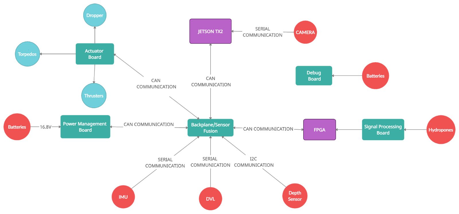
Power Management Board
As already discussed due to galvanic isolation, we powered the Thrusters with one battery and rest with the another. The Thruster battery discharged fast, decreasing runtime and efficiency. So, this year a smart battery management system was incorporated which used 2 16000 mAh LIPO battery packs but one battery at a time.After a battery discharges to a minimum preset level we switch batteries with help of a hot swap controller and a STM32f103c8t6. This board is also responsible for generation of different voltage levels,i.e. 12V,5V and 3.3V to meet the requirements of different components across our
circuit.
Backplane/Main Board
All the different boards are connected to the main board using high density connectors which are controlled by STMH745ZI-Q. This board communicates with JETSON TX2.
A high-quality, reliable Inertial Measurement Unit (IMU) is a crucial part of any autonomous underwater vehicle (AUV). Previously our AUV had to rely on accelerometer and gyroscope signals to obtain velocity and position values, which was giving lots of error in determining the exact position. So to assist our previous IMU, we are installing Doppler Velocity Log (DVL) in Makara which serially communicates to the CPU. Erroneous velocity values that are impossible or unlikely are filtered out. For samples when no values are received, the program extrapolates until a real value is received.
Furthermore, to provide an accurate way of measuring depth, a pressure-based depth sensor was also added to our AUV which communicates with STM32 microcontroller
through I2C.
Actuator Board
The AUV has a support for 10 thrusters and also we have incorporated MOSFETs to drive solenoid valves for torpedoes. We use a mix of T200 and T100 thrusters, controlled using BlueESC. We are also planning to introduce current sensors to measure the current going to individual thrusters thus helping us to get an approximate idea for speed of thrusters as we can’t have an encoder on the
thrusters.
Debugging Board
In our previous circuit, we used LEDs to debug circuits which made troubleshooting difficult and time consuming. So, in the new circuit we introduced an independent debug/protection board with an onboard OLED screen powered with an independent power supply. This board contains a STM32f103c8t6 microcontroller which monitors voltage, current and temperature at all important nodes using LTC2990. The data acquired is stored in an EEPROM which can be used for later debugging. Our circuits have also been incorporated with TPS2660x efuses to ensure circuit protection. These efuses can also be controlled by the debugging board in case of any
emergency.
Acoustic Board
In our previous bot, we tried making passive sonar for locating the pinger with hydrophone and RaspberryPi with external ADC but that did not turn out to be working. So This time we planned the whole Acoustic signal processing part based on FPGA. We designed our own Analog frontend board which Has Adjustable Bandpass filters, Amplifiers with Adaptive gain control, and High-speed ADCs which connect to the Eclypse Z7 FPGA board. We find out the pinger heading by finding the Time Delay of Arrival of signals. FPGA can communicate to onboard Computer via Ethernet or CAN bus
There is an onboard AVR microcontroller ATMEGA328p that controls the Frontend gain and filtering also controls various power rails within the board. This board has its own local power distribution to meet the special requirements of the board. The microcontroller also interfaces with the debugging board via CAN and can regulate high-performance and power-saving modes. And power down partially or fully in case of fault when signaled from debugging board.
Old Circuit
Mechanical Subsystem
Vehicle Design
Design and Material Selection
The frame is designed to be compact and modular to reduce drag force down to a minimum and provide efficient hydrodynamics. The frame design borrows some inspiration from Tesla's Cybertruck model. Aluminium is used as the material of the frame due to its lightweight and easy machining ability. The frame is trapezoidal (from the side view). The design of the frame is such that each elementary structure (hollow box and aluminium rods) can be separated from each other. It allows us a never before level of flexibility in adjusting dimensions depending upon the
requirements.
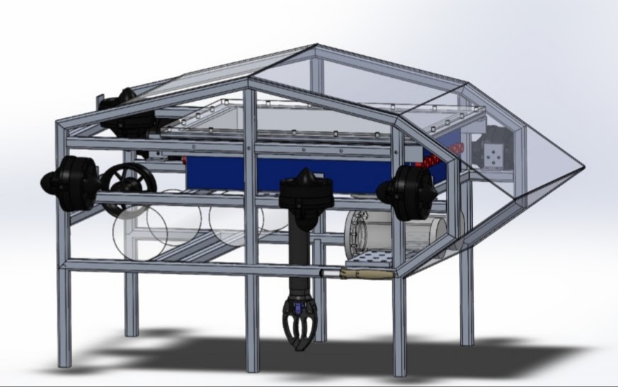
Hull Design
The hull design is aimed to provide high strength and rigidity while keeping the weight to a minimum, so we went for an S Glass box-shaped enclosure.
The hull is divided into two layers – one for electronics and circuitry and the other for battery enclosure. The material of the hull is chosen in such a way that it does not crack at a depth of about 10m. This is thoroughly tested by simulation in ANSYS Static Structural by applying hydrostatic pressure equivalent to a depth of 10m underwater.
Both its ends can be easily opened to access the electronics inside. The design also provides watertight sealing to the bot. In case of an accidental failure, the electronic components are placed on a perforated and tapered base plate. This ensures the safety of the circuit in case of leakage as the water first collects at the bottom of the base
plate.
Camera Hull Design
The camera hull is made of acrylic. So similar simulations were performed on the camera hull in ANSYS as done in the main hull to ensure structural
integrity.
Dropper and Grabber
A very simple mechanism has been employed to drop the required objects from the vehicle. In our mechanism, a BO motor is mounted to a PVC pipe. When the motor rotates, the obstruction causing the object to stay is removed, and hence the object falls. Newton Subsea Gripper, developed by BlueRobotics, is
used.
Torpedo Design
The torpedoes are in the shape of a hollow cylinder of 10mm diameter and are 3D printed for high accuracy. A pressure-based system is used to launch the torpedoes by a tank with pre-filled pressure of 30Pa. The torpedo is connected to the tank through PU fitting pipe passing through a coil actuating solenoid, which on receiving the command opens for about 10 milliseconds, thus allowing the air to pass from the tank to the torpedo through the PU fitting
pipe.
Cooling System
The thermal system consists of a quasi active cooling system.
It helps us provide better cooling without having a heavy toll on our batteries. The primary method of heat transfer is conduction. There are other minor sources of heat, which are cooled by convection due to the circulating air.
The cooling system primarily consists of heat pipes paired with internal cooling mechanisms present in some of the components. The heat pipes help in easy and continuous flow of heat out from the hull via the heat sinks present in the ICs and Jetson.
Jetson has an inbuilt cooling fan which benefits a lot from this cooling system by providing it with a viable heat sink in the otherwise closed environment.
In the earlier models, we did not emphasise a dedicated cooling system as heat released by electronic components of our previous renditions was manageable. In our new vehicle, we have used better and more powerful ICs and a Jetson, which are primary heat sources. Each is connected to heat sinks and further connected to heat pipes. Furthermore, the heat pipes are in contact with the water outside directly for further heat transfer. There is a cooling fan within Jetson that helps us circulate the air in the hull, which is in contact with heat sinks, and heat pipes help in faster cooling and allow circulation of cool
air.
Experiment Results
Analysis of the battery hull and main hull using ANSYS Static structural was done considering pressures at a depth of 10m for all possible materials taken into consideration initially.Then appropriate materials were chosen thereby giving results of factor of safety of given structures well above 3( S-Glass was chosen for main hull and battery hull) . Thermal analysis of heat pipes used in the cooling mechanism was done using ANSYS - Steady state Thermal. The cooling system proved efficient to dissipate the heat generated by the electronic
components.
Equivalent stress analysis of Battery hull
Factor of safety results for battery hull
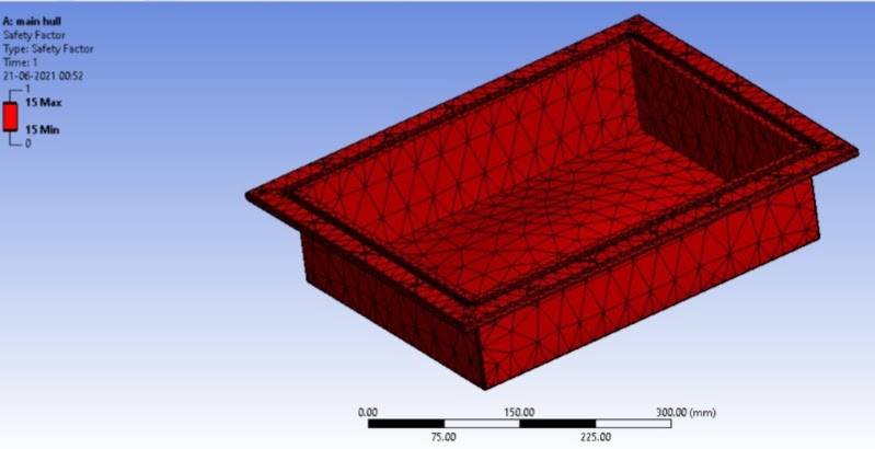
Factor of safety results for analysis of Main Hull
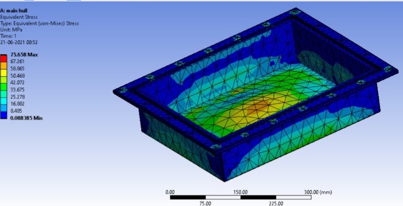
Equivalent Stress results for analysis of Main Hull
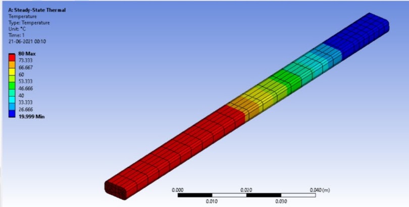
Temperature Gradient results for Heat pipe cooling ICs
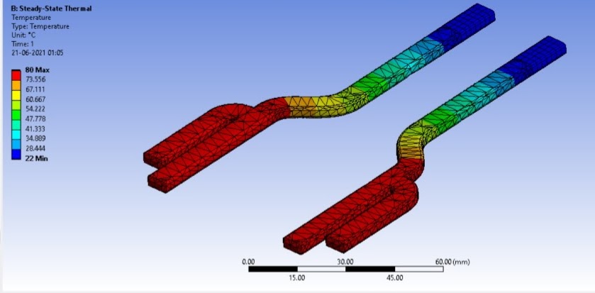
Temperature gradient results for heat pipe cooling JETSON